

[ comments ]
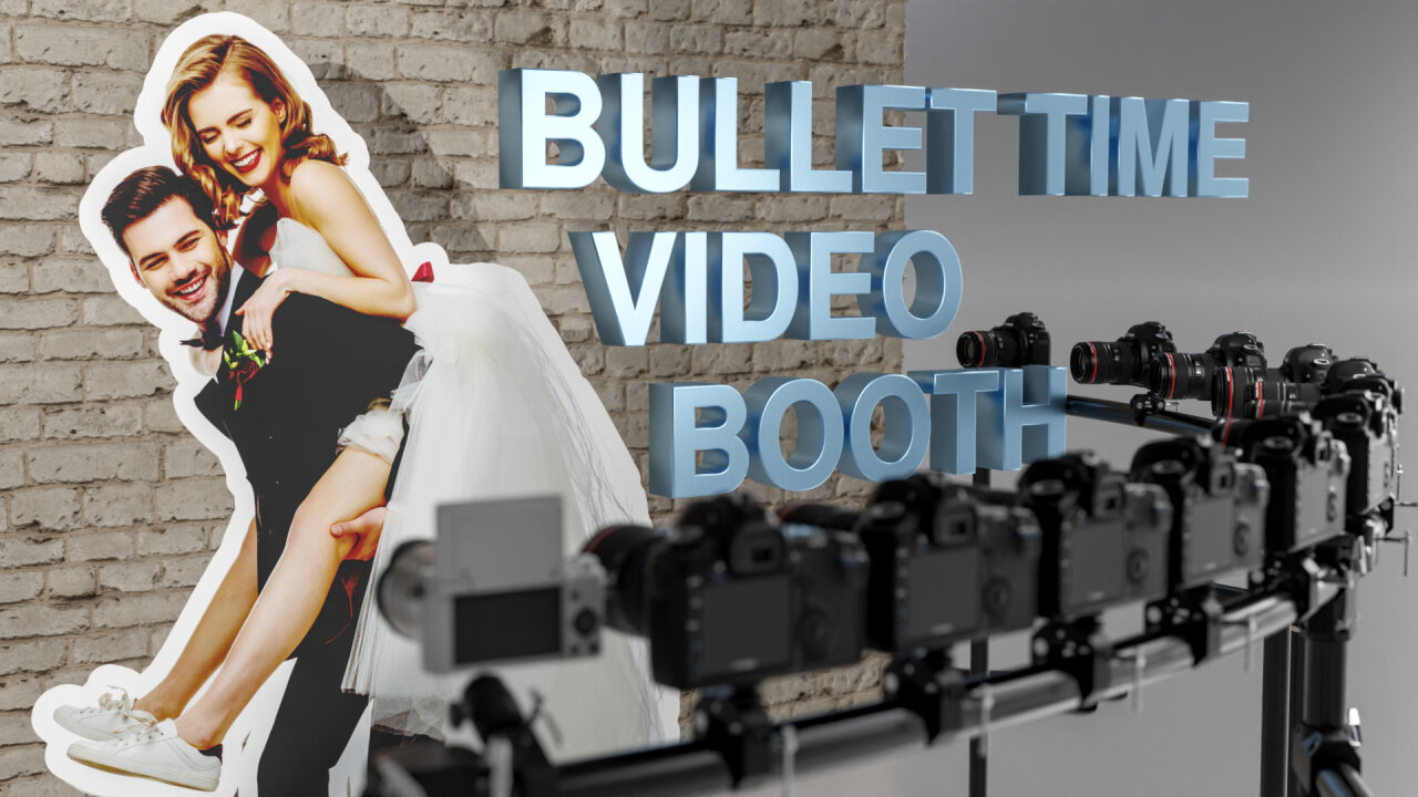
For my cousinâs wedding I did not make a photo booth but a video booth. - With an array of DSLRs to create a bullet time effect.
Since this is a very visual project, you should really watch the video. This blog post contains the same info with more details, but those details are probably only relevant if you really want to recreate this project, which is not an easy thing to do.
What is a bullet time video booth?
The story of this project actually begins in 2017 when I created a video booth for my own wedding. At many wedding receptions you can find photo booths, which are simple camera setups with a remote trigger to allow guests to create some memories of the special day. Usually this involves silly props like hats, wigs and giant glasses and it is as much about creating photos as a memory as it is about the fun of being creative while doing so. â¦and for my wedding I mixed it up a bit by putting my Sony NEX-5T on a tripod and allowing guests to take short 5 second clips instead of static photos. Later I cut all the clips into one long video with upbeat music and we still enjoy watching this memory today.
My family enjoyed it so much, that one of my cousins used the same setup a few years later at her wedding and when another cousin planned his wedding for this year, he also asked for a video booth. But this time I wanted to try something new by adding a bullet time effect.
In case you never heard of it: The bullet time effect was famously introduced with the movie âThe Matrixâ from 1999. It really became a signature style for these movies and has been copied and reused so many times that it pretty much became a movie cliché. But while it can easily be recreated in purely rendered form like animated movies or video games, it is still quite involved and costly to achieve with real cameras: You set up an array of photo cameras, trigger them all simultaneously and play back the individual photos as frames of a video. The result is that the scene seems to be frozen in time while the camera moves around freely.
And here you see the problem for hobbyists. If you are not rendering the entire scene but need to take photos of real people, this can quickly become expensive. Bullet time-time costs one camera per frame. For someone shooting with the typical âEuropeanâ 25 fps thatâs 25 cameras per second. And that of course also explains why my bullet time video booth only uses this effect for the transitions instead of recording several seconds of bullet time footage. I simply wanted to keep the costs for this project in a reasonable range by only using twelve cameras.
This means that I only have a bit less than half a second of bullet time footage per guest. But as you could see in the little example clip above (and more in the Youtube video) the effect is still nice and appears longer. To achieve this I used two tricks:
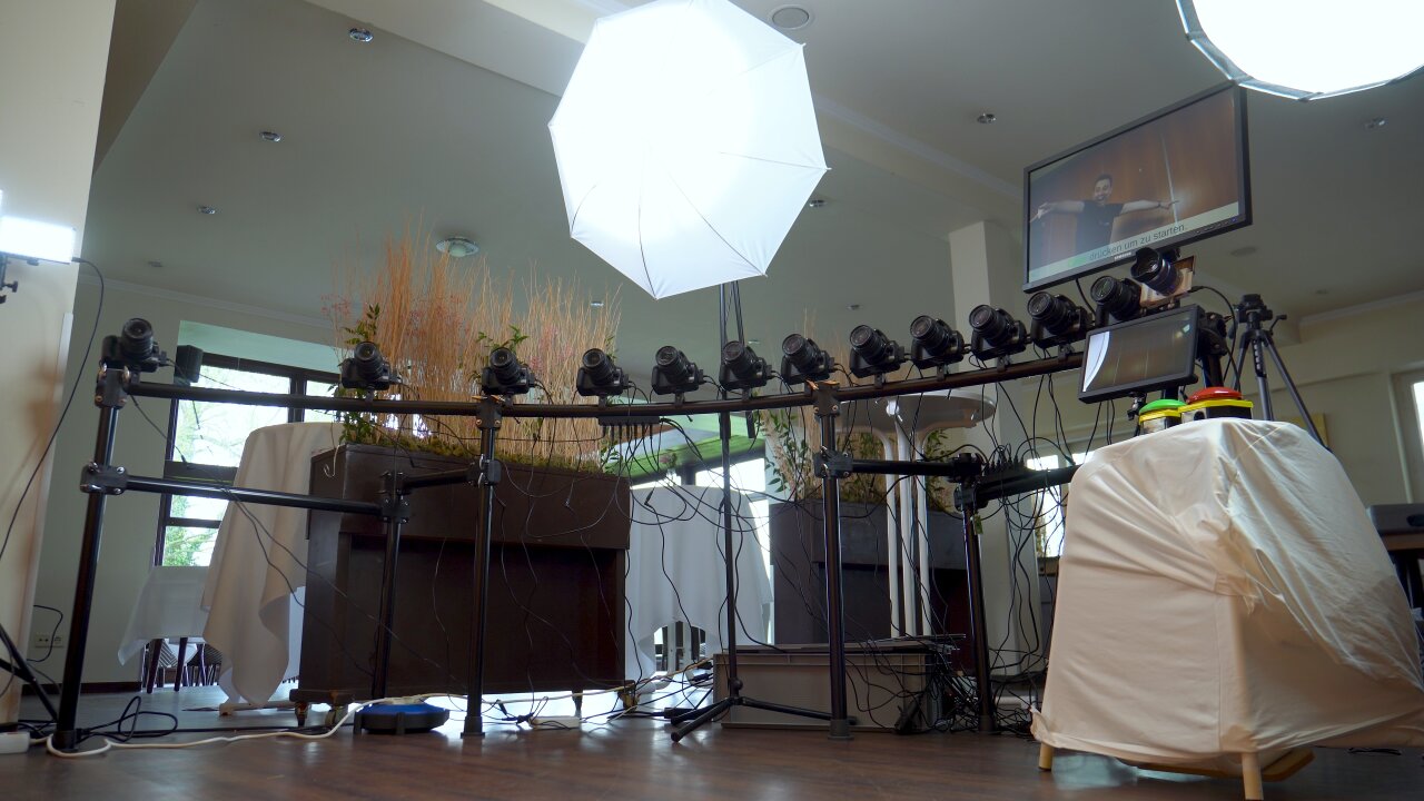
- I trigger the cameras at the beginning and the end of each video recording and they are arranged in an arch towards the wall behind the guests. By mirroring every second guest clip and playing the bullet time photos in different order I can combine the two twelve photo sequences from the end of the previous guest clip and the beginning of the next guest clip to make it look like the camera spins through the wall to the next clip. An additional blurred frame at the location where the camera would be inside the wall and a non-equidistant placement of the cameras for an accelerating motion towards the wall help to sell the effect. This adds up to 25 frames and therefore one second of bullet time footage.
- I created the final video of all guests (and the example above) in DaVinci Resolve and used its Optical Flow Estimation to generate artifical additional frames. This allows to smoothly slow down the bullet time effect further and also gradually slow down the video recording after leaving a bullet time transition and before entering the next bullet time transition.
So, I was able to pull this of with twelve cameras plus the one for the video recording. But this setup requires more than just the camerasâ¦
Setup
In this section I will go through the important components of the bullet time video booth. Keep in mind that pretty much everything was selected to keep the costs as low as possible. Unfortunately, this also means that some components were a bad decision in hind sight and some components are simply more expensive or better equipment which I happened to already have. So, if you want to build something similar, be prepared to pick your own components and adapt the software to your needs.
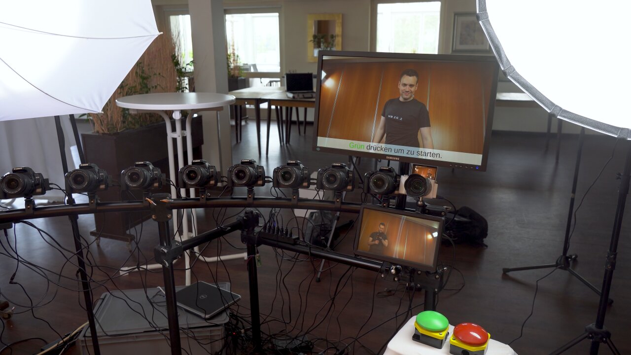
Bullet time camera array
Letâs start by looking at the part that obviously is the most expensive because that purchase comes with a factor of twelve: The cameras used for the bullet time effect.
When I said that the bullet time effect is still expensive, I have to admit that it has become much cheaper since 1999. Cameras have become so readily available and good today that a comparison to 1999 equipment would be ridiculous. Still, I set myself a limit of 50⬠per camera, which means that the twelve cameras alone would cost 600â¬, which I find quite heavy for a fun gimmick to a video booth. And now think about what cameras you can get for 50â¬â¦ There are some possibilities like webcams, used smartphones, used action cams, etc. But used ones for 50⬠will have poor image quality and their small sensors are not ideal for this effect as they require more light for short shutter speeds or you will get a lot of motion blur. Raspberry Pi cams are also an interesting alternative in the maker world, but the cheap ones have very poor image quality and the better ones cost 50⬠alone without a lens - and you need a few actual Raspberry Pis which are even more expensive.
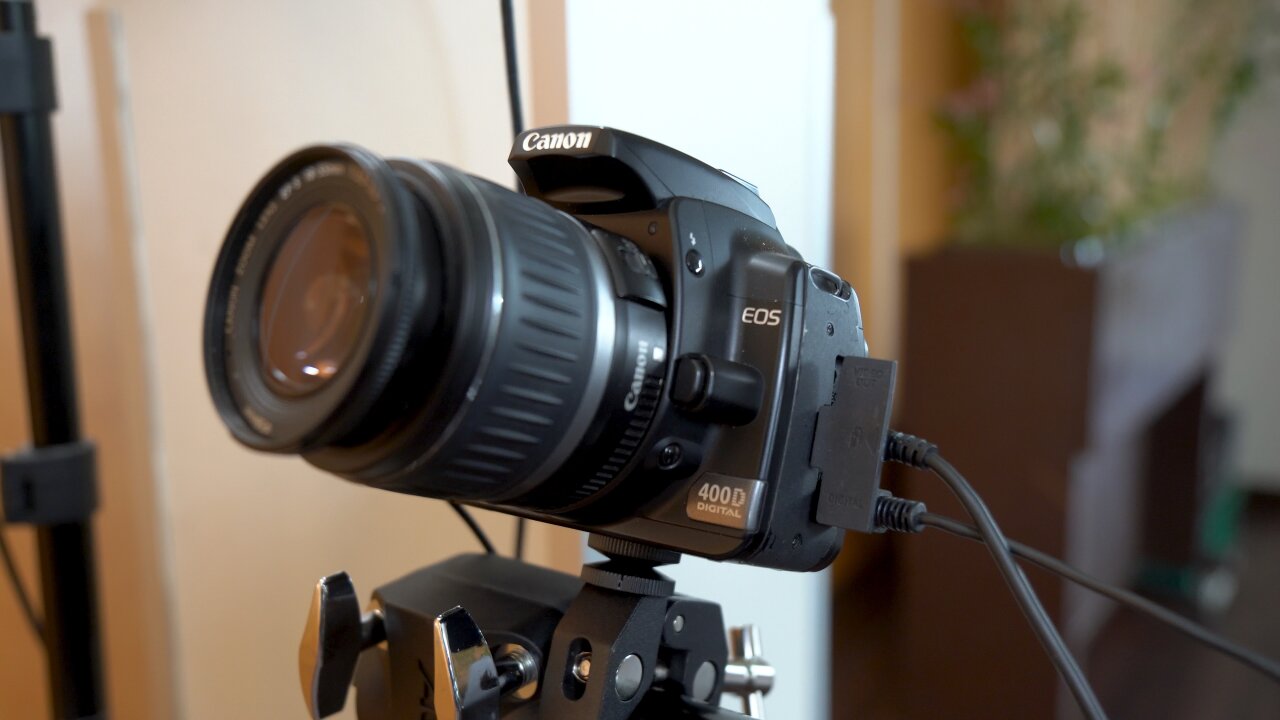
Instead, I looked for old used DSLRs. They have large (albeit old) sensors, they support means to remotely trigger the shutter, they have plenty of resolution, their settings can be controlled precisely and nobody except me is interested in them anymore. The trick is that we are using the photo mode of these old DSLRs to create a video, which means that we are comparing old photo specs with modern video specs. So, I looked for the oldest mainstream beginner DSLR that has a decent resolution and picked the Canon EOS 400D from 2006.
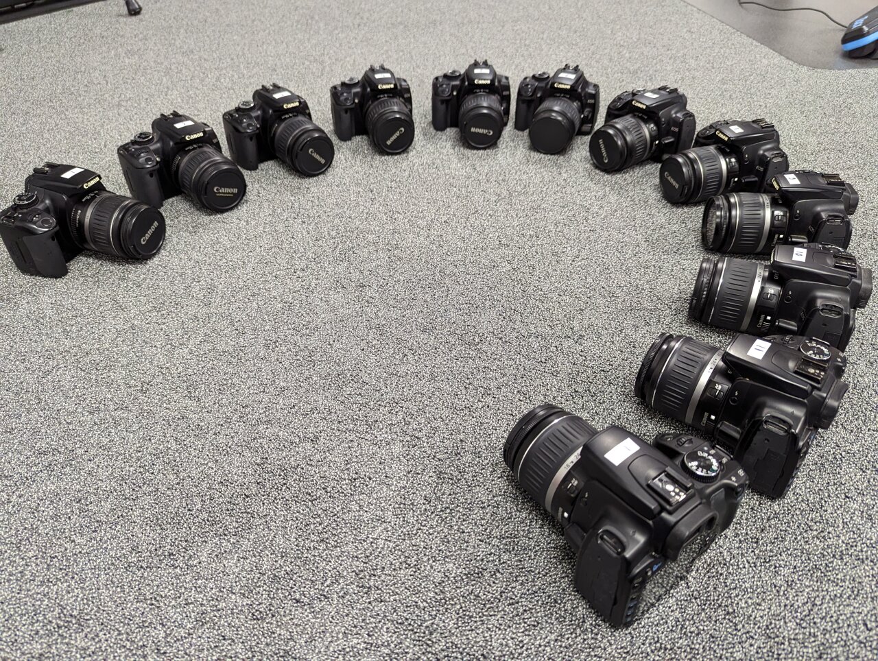
That camera is now almost 17 years old, which means that craigslist is full of those cameras. There are so many people trying to sell their old camera with almost nobody being interested in such outdated technology that I could simply work through the offers starting with the oldest listings. I offered my 50 bucks for the 400D and its mediocre kit lens, reminded the seller that nobody has even looked at the listing in six months, and either he accepted or I contacted the next one in the list.
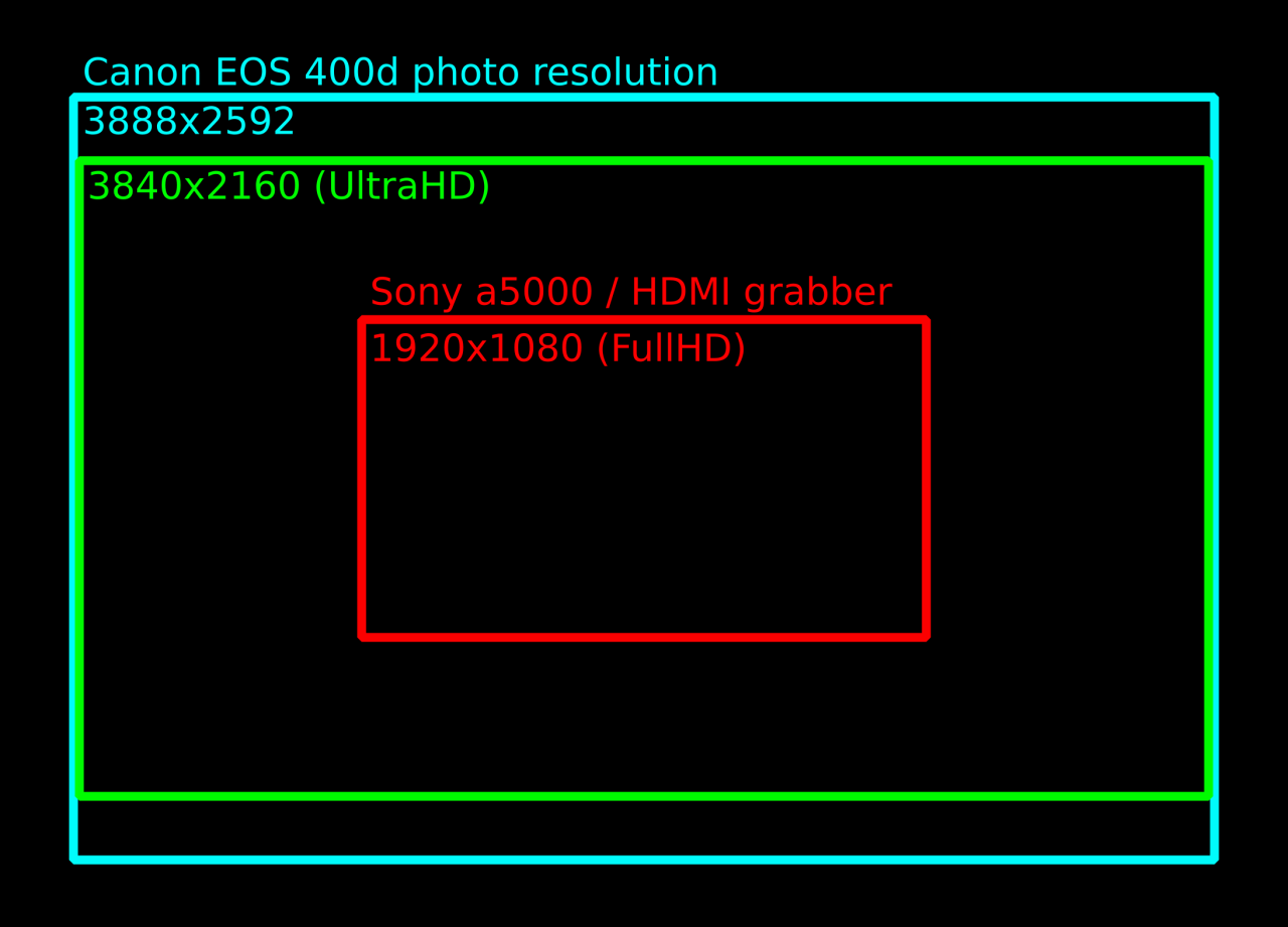
But is it good enough? Well, thatâs where we can now compare the photo specs to the video specs. The old 400D from 2006 has a photo resolution (it cannot even shoot video) of 3888x2592 pixels, which is more than our modern 4k (or actually UltraHD) video with 3840x2160.
Video camera
But since the Canons cannot record video I need one more camera as the main camera that shoots the video. Initially, when I selected the 400Ds, I aimed for 4k video and planned to use my trusted Sony a6400 for this. Unfortunately, it turned out to be rather difficult to trigger the video recording precisely and transfer the resulting video file. Both can be done via USB, but one requires the camera to be in control mode and the other one requires it to be in mass storage mode. Video files apparently cannot be transferred in PTP mode, which seems to be an oversight by Sony.
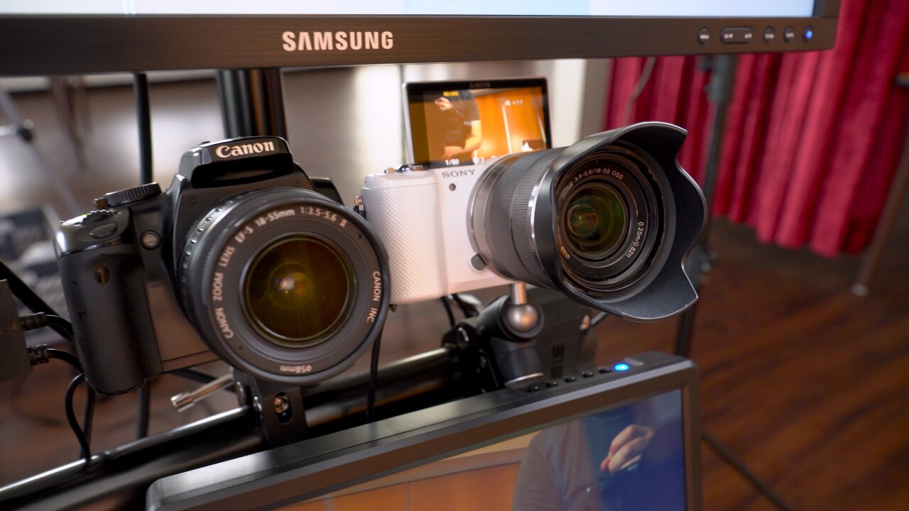
I either needed to use a Wifi SD card like I did in my old original video booth or record externally with an HDMI grabber. Since transferring 4k videos with a Wifi card (or maybe even recording to that old Wifi SD card) seemed like a bad idea, I dropped the 4k goal and went with one of my cheap 1080p HDMI grabbers instead. And since I did not need to tie up my good camera in this project if I only record 1080p footage through a mediocre HDMI grabber, I used my Sony a5000 instead. Some of you might remember it from an older post, because it requires a hack to get a clean HDMI signal.
So, we are down to FullHD, but as a plus using an old cheap camera gives me some valuable peace of mind when leaving the bullet time rig unattended at the wedding venue.
Quarter circle stand
At that point I thought that I had bought the most expensive part of my bullet time rig - until I faced the question of how to mount the cameras. Whichever solution comes to your mind right now: Remember to multiply its cost by twelve and think again.
Using twelve individual super-cheap tripods is impractical as someone will easily hit one of the tripod feet and misalign a camera from the other ones. So, I was sure that I need a common stand to which I mount all cameras. I first thought of traverse material as found on stage, but that is super expensive. The next idea was to build something myself out of plywood when I stumbled upon a B-stock e-drum rack. Specifically, it was a rack for the Alesis Strike Pro SE. On its own this is not ideal because its components are not enough to form a proper quarter circle and the horizontal bars are not mounted at the same heights. But I got that B-stock rack and a new one for a total of 93⬠and combined them in a different arrangement. This even left a few spare parts that I could use to mount a screen to the setup.
Unfortunately, that was not the end of the problem, because I still needed to mount the cameras to the rack. Thatâs where I went for a solution that was too cheap. I got cheap clamps from aliexpress (which were fine) and attached them to the cameras with simple threaded rods and cheap threaded plates. My thought was that twelve cheap ballhead mounts are quite expensive in total and that instead I could rotate the clamp around the rack bar and adjust the second axis by tightening the threaded plates. Unfortunately, I ended up just tightening the clamps to the cameras until the threaded plates cracked, which worked ok that one time, but if I want to use the setup again, I need to replace all plates - and probably buy twelve of those cheap ballhead mounts after all.
Power supplies
Another bad solution that I cannot recommend is the power supplies. You obviously donât want to rely on batteries, so a set of dummy batteries from aliexpress had to be purchased (again, factor twelve - you see how this adds up?). For some reason I thought that getting ones that plug into USB ports instead of AC outlets would be a good idea, although both need to convert the voltage to the cameraâs 7.4V. The tempting idea was that I could just plug all cameras into two 8-port multi chargers.
That was until I did my first tests and the cameras reset instead of taking a picture. At least when I triggered all twelve cameras simultaneously. Because in that case the chargers could not keep up with the sudden surge current and were unable to provide the proper voltage for the cameras. I think the problem here is that these old DSLRs need next to no power in standby as they do not show a live view. But when triggered, they have to move the mirror as well as the shutter while suddenly reading and processing the sensor - and they were designed with a Li-Ion battery in mind and not a cheap USB-based converter. The chargers on the other hand expect a more or less constant high current draw from a device that actually buffers sudden power demands with its own battery.
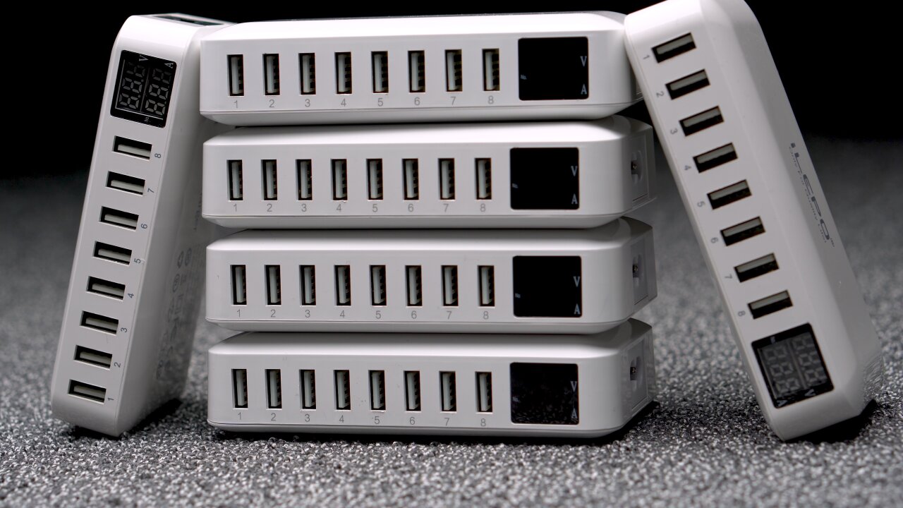
Regardless of the cause of the problem I tried many chargers and most of them struggled with the triggering cameras. In the end the multi-charger was the most reliable one if only two cameras were connected, so I ended up buying six of these multi-chargers, which of course was way more expensive and inefficient than using dummy batteries with individual AC power supplies in the first place.
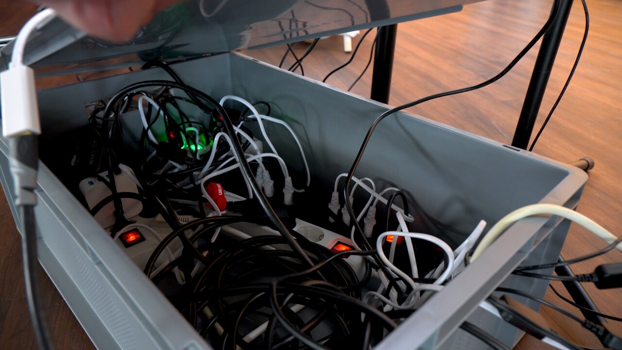
USB connections
And while we are talking about USB problems, the data transfer was not any easier. I connected the twelve cameras through two active USB hubs. I think this is close to the limit of what you want to manage as a large web of USB cables. Larger projects should instead use a few Raspberry Pis and connect via ethernet, but twelve cameras plus a Rapberry Pi Pico (see next section) plus the HDMI grabber (on its own USB bus) should be managable, right?
Well, it worked on a Raspberry Pi 3 which I first used as the brain of the bullet time rig. I had some electrical issues like the entire USB bus resetting when I turn on the fluorescent lights in my basement, but in principle I could control and read-out all cameras reliably. But since the Pi 3 was too slow to generate a preview in under a minute I replaced it with an old Dell XPS 12. And suddenly I could not use all USB devices at the same time.
After some research I learned that the Intel xHCI USB3 host controller in that device has a limit of 96 endpoints and that USB3 uses (at least) three endpoints per device. Thatâs still plenty? Well, donât forget that each USB hub and all internal USB devices like the laptopâs Wifi module, Bluetooth module, webcam, sensor hub and internal USB hubs count towards that limit. In the end, after blacklisting some devices (no BIOS option to disable the webcam) I still had one device more than the controller could handle.
The solution? Connecting the USB3 hubs through a cheap USB2 cable. Seriously. That forced the devices into USB2 mode, reduced the number of endpoints and solved the problem.
Camera trigger
Ok, so at that point we have all cameras mounted, they have power and they can be controlled via USB. Thatâs it, right? Not necessarily. You can trigger the cameras via USB and thatâs what I tried first. But I found that this was not reliable and precise enough and that some cameras would trigger with a minor delay. Not much, barely noticable from the sound of the camera shutters, but if you play back the photos as a bullet time clip, you would notice that some photos were taken at slightly different moments in time - at least if there is fast motion in front of the camera.
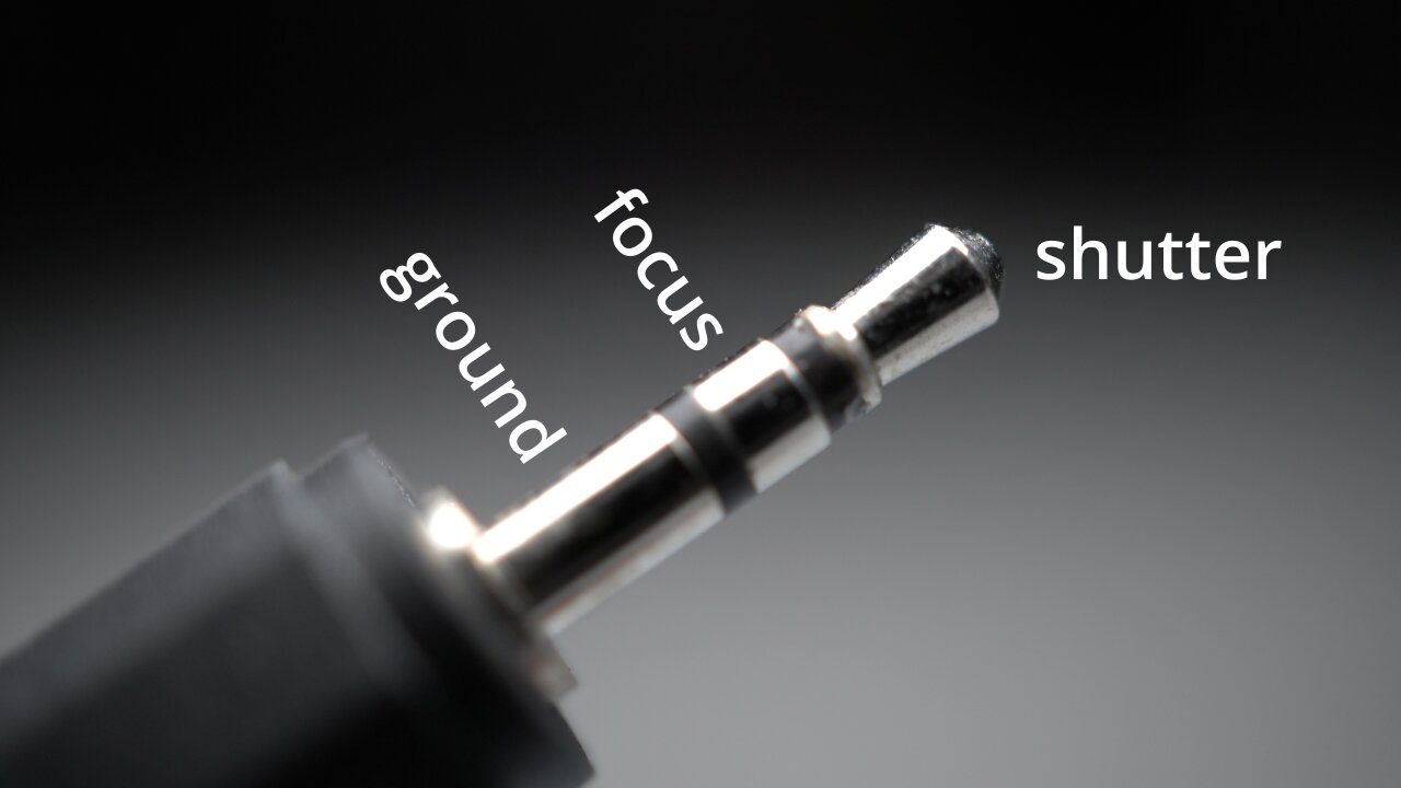
So, instead I used the trigger inputs of the Canon cameras. These are fairly simple: It is a smaller TRS audio jack with a common ground and two contacts that control the autofocus and the shutter. These two contacts are pulled up to 3.3V by the camera and if you connect them to ground they signal the camera to focus or to trigger, respectively.
If you want to build a proper solution, you would now design a little circuit for each camera that decouples this electrically via optocouplers which in turn you control through some simple transistors and a GPIO pin of the microcontroller of your choice. If you are lazy, you simply connect all trigger inputs in parallel directly to the GPIO pin, set it to open drain mode to avoid it fighting with the cameraâs logic level and let it drive all twelve pins to ground through a common connection.
I chose the lazy solution.
The advantage of this is that you can use cheap audio splitters and a bunch of cheap audio cables to connect all twelve cameras. Everything, including the GPIO connection, is just connected in parallel.
The disadvantage is electrical issues as all camera logic levels are connected through their pullups and all grounds are connected through the trigger cables as well as the USB spaghetti and dummy batteries with their voltage converters and USB chargers. You can tell that this is not how these triggers are meant to be used when you notice that all cameras trigger randomly if one of the cameras is turned off. This is an electrical nightmare and probably also part of the reason that the USB bus resets when I turn on the lights. I cannot really recommend doing this. â¦but it works.
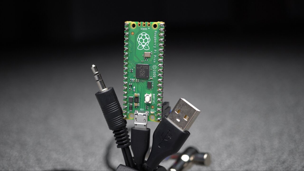
Oh, the code for the Pi Pico of course is as simple as it can get, but if it helps you can get it from my github repository.
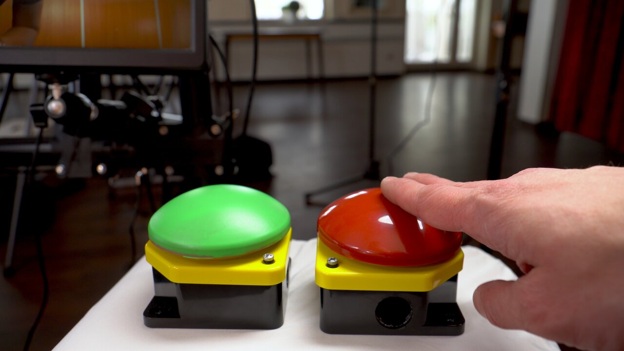
Bluetooth push buttons
A part that I am actually somewhat proud of are the big push buttons. Not because they are such an intricate design, but because they are mostly a spontaneous solution that worked perfectly. I left them for the end of the project thinking that I just need to add cables and connect them to one of the many GPIO pins of the Pi Pico that also controls the shutters. But when I got to that point I was uncertain on where the buttons would be placed at the wedding reception.
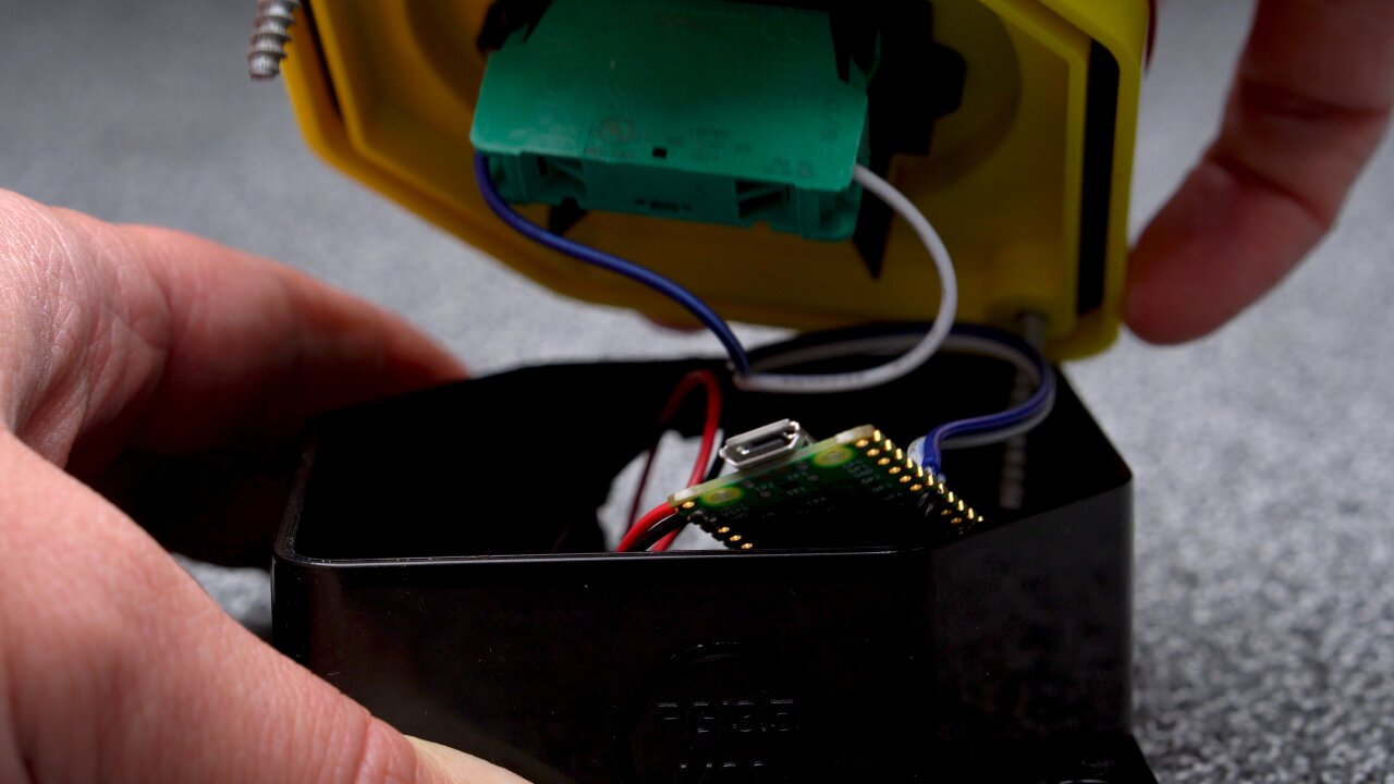
So, I spontaneously decided to make them wireless. And since I am not a fan of keeping a stock of Li-Ion batteries and also wanted to be able to have spare batteries available if necessary, I wanted to use good old AA batteries. So, I checked my stock of microcontrollers, ruled out the ESP32s which are a bad mix with AA batteries and found the Raspberry Pi Pico Ws that I bought with another electronics order and had not used yet.
These are cheap, can easily run on two AA batteries and have a Bluetooth module on board (like the ESP). They are also small and easily fit into the buttons together with the batteries. Only problem: Their Bluetooth module has only been implemented recently and it is still a bit tricky to get this set up. Also, Bluetooth is currently only available in the C SDK. But once I figured it out I had two big push buttons, running on AA batteries all night long. They connect to any device that supports Bluetooth Low Energy as a normal HID interface, i.e. they act as a normal Bluetooth keyboard that only has a single button.
Only bad news is that the licenses for the Bluetooth example that I used have not yet been adapted by the Raspberry Pi foundation. By that I mean that my code is based on hid_keyboard_demo.c of the Blue Kitchen Bluetooth stack, which is currently only referenced by the Raspberry Pi Foundationâs pico-examples repository. While some rumors speak of an upcoming maker-friendly license, the demo is currently only available under the Blue Kitchen license, which explicitly prohibits any redistribution for commercial purposes. Since I receive ad revenues for my projects (i.e. Youtube) I cannot claim that there is no commercial purpose and hence I am not allowed to share my code at this point.
If the code is eventually released under a more permissive license, please let me know and I will happily share the changes I made.
Until then, it is not too tricky to adapt hid_keyboard_demo.c. Connect the push button such that a GPIO pin is connected to ground by the button, enable the internal pullup of that GPIO pin and modify the demo such that a keypress is sent when the GPIO pin goes low.
Lights
Last but not least, you cannot neglect the lights. On one hand you want your shutter speed to be short enough to avoid motion blur from jumping guests. On the other hand you also do not want to use any auto-mode of the cameras. You want to avoid auto-focus, auto-exposure and auto-whitebalance, because the cameras would get different results and the pictures from each camera would be slightly different, which in turn would lead to flickering when playing them back in sequence.
So, you have to manually focus all lenses to a fixed spot and you either have to set the exposure and autobalance via USB for all cameras and automatically adapt it to changing light of the environment as the sun sets - or you bring controlled lights that dominate the other lights, so you can work with a fixed exposure and whitebalance through the entire day and night.
I already had a selection of video lights from the Aputure Amaran series and brought a 200d (200W COB LED light with a light dome attached), a 60d (60W COB LED light with an umbrella), an HR672C (larger LED panel) and two F7s (small LED panels). That wonât impress a professional videographer, but itâs a decent collection for a hobbyist and still I could notice some color shifts when the sun hit the windows of the room during sunset.
Oh, and donât forget to think about the impact on the actual wedding reception. In this case I was lucky as I could set up the video booth in a separate room that was not used at that time and everyone became curious because of the bright white light that came from the door to the other room. But if you are in the same room as the dance floor, people will not be happy if you kill the mood by bringing your own personal sun without shielding it somehow. Just sayinâ.
Software
Well, that was the difficult part. In contrast to some other projects, figuring out the cheap solution and getting all the hardware was indeed more time consuming than implementing the software. Besides the two minimal firmwares for the Raspberry Pi Picos (the camera trigger and the push buttons) the software only consists of a bit of Python code, which you can grab from my github repository.
As mentioned above, the brain of the bullet time video booth is an old Dell XPS 12. This is definitely not an ideal device here as it is an older convertible laptop without particularly impressive processing power. In fact, this might be one of the worst laptops I ever owned since I never really used it in tablet mode and it had a lot of shortcomings when you think of it as an expensive laptop. But it was not in use and had significantly more processing power than the Raspberry Pi 3 that I tried to use first.
The thing is that this device shows the interface to the guests, which is either a simple countdown or an idle loop of previously recorded bullet time clips from other guests. But it also has to retrieve the photos from the cameras, record the stream from the HDMI grabber and convert the photos and that stream into video clips for a preview and that idle loop. On the Pi 3 it took more than a minute to create a 720p preview while the guests waited to see what they just recorded. On the XPS 12 it takes 20 seconds, which could still be improved with a newer device, but which is bearable for the guests.
The conversion to video clips is not a simple concatenation in ffmpeg. In order for the bullet time effect to look good, the cameras have to be aligned perfectly, which is nearly impossible with the cheap mount solution that I picked. Also, you have to expect that the alignment will not remain perfect throughout the entire wedding reception as guests might accidentially bump into cameras. So, instead of trying to achieve a perfect alignment, I made sure that the focal length of the bullet time cameras is a bit shorter (i.e. wider viewing angle), so that I can align and crop the resulting images later. This is the same as image stabilization for a video with the benefit that a misaligned frame does not come with additional motion blur. So, I used ffmpegâs image stabilization for the clips that were generated on-site (preview and idle loop).
The filters in ffmpeg also came in handy to create what I call a âPseudo in-wall frameâ. That additional blurred frame at the location where the camera would be inside the wall, which I mentioned earlier. This is simply the photo from the camera closest to the wall, shifted slightly so that the wall is in the center of the image. A strong directional blur then masks the fact that the perspective is still far from the wall and only leaves a wall-colored smear that sells the idea of the motion blur that you might see if you could actually move through the wall.
The entire thing is implemented in Python and uses gphoto2 to communicate with the cameras via USB and an ffmpeg-wrapper module to generate the preview clips as well as the higher quality 1080p clips that are shown while the booth is not being used. The interface however is implemented in Flask and shown in Chromium. The reason for this is that the video players in webbrowser are among the best players in terms of performance and frame-precise playback. Since the clips are shown randomly during the idle loop they have to alternate between the mirrored and regular version and in order to sell the impression of the camera moving through the wall, the next clip has to start playback precisely on the last frame of the previous clip. This can be achieved with two HTML5 videos that alternate their playback state, so that one can preload the next clip while the other one is visible and playing. With one of the players being mirrored with a simple CSS transformation and without any noticable performance cost, the alternating flipping comes naturally in this system.
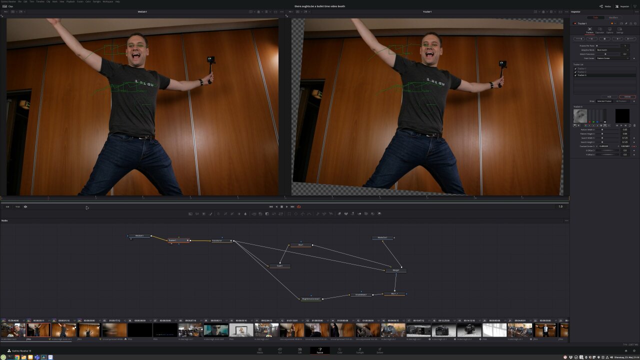
Post-processing
Now, there is one last step missing to get the bullet time clips from the preview above. The ffmpeg version only generated a rather generic image stabilization by trying to stabilize the entire image, which includes countering the apparent rotating motion of the camera. Instead we want to stabilize the central point around which the camera moves. This is something I had to do manually in post using DaVinci Resolve. I used a simple tracker and a bullet time clip in which a person stood quite precisely in the place that should be the pivot point for the camera rotation. I tracked some features on the person and stabilized them while also zooming into the footage slightly to avoid black corners around the repositioned images.
There is no reason to do this tracking for every clip, as the solution of the reconstructed camera motion can simply be applied to all other bullet time shots as long as the cameras have not been moved. So, I only had to do this three times for the entire footage from the reception when a guest bumped into a camera and changed its alignment. In the end there were some cameras that were so misaligned that black borders were no longer avoidable and I masked this with a blurry scaled copy of the orignal image behind the stabilized one.
Another important processing step in DaVinci Resolve is adding additional frames. The one second bullet time transition generated with ffmpeg on-site already looked quite nice, but with optical flow estimation it is possible for many clips to add almost perfect additional artificial frames. So, I set up a slowed down version with Resolveâs Time Warp feature, which does not work for every scene and sometimes creates obvious artifacts, but which helped to really bring out the bullet time effect for scenes on which it worked nicely.
In the end my cousinâs guests recorded more than 100 clips, which I had to edit into a longer video. Luckily, DaVinci Resolve can be automated with Python, so I set it up to automatically generate stabilized versions of all recordings with different amounts of additional artifical frames. This means that I had a collection with different variants of each clip, so I could pick which version looked best and also which had the right duration to match different music tracks. So, of course, not every clip ended with a bullet time transition as slow as shown in the demo above. In the end, nobody would want to sit through a video with a hundred of those, but it helped to showcase some really cool transitions with airborne kids, flowing hair and flying items.
Conclusion
At this point I have to say that the final video worked out even nicer than I had hoped for. In fact, the part that bugs me most in the end is that this ugly wood panel wall in the background really downgrades the final look, but that could not be helped. If there is a next time (as in another occasion, not as in that same cousin marrying again) I should prepare a backdrop. Before the actual wedding I was really worried that I would spend a lot of time debugging and fixing things instead of celebrating with my family, because there were so many things that failed during tests. In the end there are 13 cameras in a rather naive electrical setup and if any one of them got stuck or had any other type of problem, the shots would be ruined. I had to deal with loose memory card covers that turned off a camera, a lose contact in one of the dummy batteries, some cameras dropping out due to a bad USB cables and of course all the troubles I had until I had enough power supplies to get a somewhat stable voltage when the cameras are triggered.
I got really lucky that none of this happened on that particular day. I had included a simple recovery code that detects unresponsive cameras and tries to reconnect the USB hub with all the cameras while warning the guests to wait a minute or call me if the issue persists. According to the recordings and what I heard from the guests this happened once, but I did not have to personally tend to it even once.
Still the point is that you should not try to set this up for your own wedding. Someone with some spare time and the appropriate knowledge should be ready to spontaneously fix things, which usually does not apply to the bride or groom. If you want this for your wedding, ask a nerd friend to look after it and if you want to build this for a friend, make sure that you have time to fix things on site.
But if it works, this is a fantastic alternative to the traditional photo booth. You can be sure that guests have never seen something like this before (well, unless my Youtube video becomes more succesful than I would expect), they will have a lot of fun posing in front of the camera array and playing with the bullet time effect (especially later in the evening) and the happy couple really enjoys watching the result and sahring it with their guests after the wedding.
[ comments ]